

High Precision Shunt Resistors: Top Selections for Accurate Current Measurement
2026-07-05
When every milliamp matters, your current measurement is only as good as the shunt resistor you choose. High precision shunt resistors are the unsung heroes behind accurate energy monitoring, battery management, and power conversion—yet picking the wrong one can silently derail your design. At Milliohm, we understand that low ohmic value doesn’t mean low impact. In this guide, we’ll walk you through the top shunt resistor selections that combine tight tolerance, low TCR, and robust construction, ensuring your readings stay true even when conditions get tough.
Why Precision Matters in Shunt Resistor Selection
When measuring current with a shunt resistor, even the smallest deviation from the stated resistance value can throw off your entire system. A resistor labeled 1 milliohm but actually measuring 1.05 milliohms introduces a 5% error directly into current calculations. In battery management or motor control circuits, that seemingly minor mismatch translates into inaccurate state-of-charge estimates or torque readings, potentially leading to premature system shutdowns or reduced efficiency. Precision isn’t just a nice-to-have—it’s the foundation of reliable sensing.
Temperature drift adds another layer of complexity. A low-cost shunt with a 100 ppm/°C temperature coefficient might see its resistance shift by 10% over typical operating ranges. That means the current measurement drifts moment by moment as the board heats up, making real-time compensation a nightmare. Tight tolerance alone won’t save you if the material properties change under load. Designers who sweat the details here end up with consistent performance across climates and thermal conditions, avoiding the field failures that become support headaches later.
Beyond immediate accuracy, long-term stability defines how trustworthy your readings remain after months or years in service. Some alloy shunts can oxidize or creep mechanically, causing permanent resistance shifts. That silent drift undermines predictive maintenance algorithms and makes energy usage tracking unreliable. By selecting a shunt with both high initial precision and proven durability, you’re not just hitting today’s specs—you’re building a measurement backbone that stays dependable through the product’s entire lifecycle.
Key Specifications That Define High-Accuracy Shunts
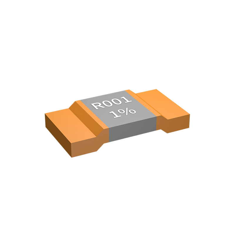
High-accuracy shunts are built around a few non-negotiable parameters that separate lab-grade instruments from ordinary current-sensing resistors. The temperature coefficient of resistance (TCR) sits at the top of the list—shunts meant for precise measurement exhibit TCR values below 10 ppm/°C, and often as low as 2 ppm/°C, ensuring drift stays negligible even as the ambient temperature swings or self-heating kicks in under load. Equally critical is long-term stability, or repeatability: a shunt that cannot hold its calibrated resistance value over months of cycling and thermal stress introduces errors no correction algorithm can fully remove. The best designs use carefully selected alloys like manganin or zeranin, which inherently resist aging and hysteresis, and their resistance element geometry is optimized to minimize stray inductance and parasitic voltage drops across the sensing path.
Power rating and the resulting self-heating effect are constant design battles in high-accuracy applications. Even a 0.1% drift from a few degrees of internal temperature rise can ruin a 0.02% system-level accuracy target, so shunt ratings are always specified with a massive derating margin—often using a shunt rated for 10–20 times the actual steady-state current. Physical construction matters here: four-terminal Kelvin connections become mandatory, not optional, because they separate the current-carrying nodes from the voltage-sensing nodes, virtually eliminating lead resistance errors. In shunts meant for DC and low-frequency AC, the voltage drop is typically kept to 50 mV or 100 mV at full-scale current, balancing signal-to-noise ratio against heat generation. At higher frequencies, AC characteristics like bandwidth and phase shift can dominate. A shunt with a flat frequency response into the hundreds of kilohertz requires a carefully designed coaxial or planar structure to counteract skin effect and proximity loss.
Finally, the mechanical and environmental specifications are too often overlooked. Mounting strain, humidity, and thermal expansion mismatches between the resistive element and its terminals can all produce micro-strain in the alloy, shifting resistance by tens of ppm. High-end shunts address this with floating or compliant mounts and hermetically sealed bodies. Calibration traceability is another hidden specification: unless the shunt comes with an unbroken chain of accredited calibration data and defined uncertainty contributions, its absolute accuracy remains an assumption. The most reliable shunts are calibrated with DC or AC-DC transfer methods at the exact currents and frequencies of use, and the report captures not just the measured value but the expanded uncertainty at a given confidence level—turning a component into a true transfer standard.
Material Innovations Driving Low TCR and High Stability
Advances in alloy composition are at the heart of achieving near-zero temperature coefficient of resistance (TCR) while maintaining long-term stability. By carefully balancing elements such as nickel, chromium, and aluminum, manufacturers create resistive films that exhibit minimal drift under thermal cycling. These precisely engineered materials rely on controlled impurity levels and optimized crystalline structures, which reduce scattering effects that typically degrade performance. The result is a resistor that maintains its specified tolerance across a wide temperature range, making it ideal for precision analog circuits and feedback networks.
Thin-film processing techniques have also seen breakthroughs that directly impact TCR and stability. Sputtering and vapor deposition methods now allow for sub-nanometer control over film thickness and uniformity, eliminating micro-voids and grain-boundary imperfections. Post-deposition annealing in inert atmospheres further stabilizes the resistive layer, relieving internal stresses and encouraging grain growth that locks in a low TCR. These manufacturing refinements ensure that every batch of resistors meets rigorous reliability standards, even after thousands of hours of operational aging.
Substrate and passivation innovations complement the active material improvements. High-purity alumina or silicon substrates with matched thermal expansion coefficients prevent stress-induced resistance shifts, while advanced passivation layers shield the resistive element from moisture and corrosive gases. New composite coatings, applied via atomic layer deposition, provide hermetic sealing without introducing stray capacitances. This multi-layered defense preserves the pristine properties of the resistive material, extending the lifespan and accuracy of components in harsh environments such as automotive underhood electronics or aerospace instrumentation.
Thermal Management Strategies for Consistent Readings
Sensor drift often stems from fluctuating temperatures, so stabilizing the environment around your device makes readings far more repeatable. Simple passive methods like adding insulating enclosures or thermal mass can dampen rapid swings, while active strategies such as Peltier-based cooling or PID-controlled heaters lock the module at a fixed operating point. The choice between passive and active usually comes down to power budget and how tight your tolerance really is.
Placement and airflow matter just as much as the hardware itself. Positioning heat-dissipating components away from the sensing element prevents localized hotspots, and thoughtful board layout can channel heat along dedicated paths. In fan-cooled systems, baffles or ducts may be necessary to keep turbulence from introducing noise. Sometimes the simplest fix is a copper pour that spreads heat evenly, turning a messy thermal gradient into something predictable.
Calibration schemes work best when paired with solid thermal design. Rather than relying solely on software compensation, build a warm-up routine into your startup sequence and log temperature alongside readings for post-processing. If field conditions are harsh, consider potting the sensor assembly or using a sealed, gas-filled chamber to buffer against ambient shifts. A well-managed thermal landscape doesn't just improve consistency—it extends the lifespan of the electronics by reducing stress.
Real-World Deployment: Placement, Soldering, and Layout
When moving from prototype to production, component placement isn't just about minimizing board space—it's about respecting the physical realities of assembly and rework. High-density designs force us to consider access for tweezers and hot-air tools, especially around fine-pitch ICs and small passives. Placing decoupling capacitors on the opposite side of the board directly under a BGA might look elegant, but it becomes a nightmare if you need to replace one. Even subtle choices, like grouping similarly sized components to reduce pick-and-place head changes, can shave seconds off assembly time per board—something that matters deeply at scale.
Soldering isn’t a one-size-fits-all process. Wave soldering, reflow, and selective soldering each have their place, but the wrong choice can turn a reliable design into a field-failure generator. For mixed-technology boards with through-hole connectors and surface-mount sensors, the sequence matters: reflow the SMT side first, then hand-solder or wave-solder the through-hole parts, being mindful that heavy connectors can act as heat sinks and cause cold joints if not preheated. Flux selection also plays a quiet but critical role—no-clean fluxes simplify post-solder cleanup, yet their residues can absorb moisture and become slightly conductive over time if not fully heat-cured. Board finish, from HASL to ENIG, further influences solder wetting and long-term joint integrity, especially in high-vibration environments.
A good layout is more than trace routing; it’s an exercise in managing thermal paths and mechanical stress. Power components need copper pours not just for current capacity but for heat spreading, and that unintentionally turns the PCB into a structural element. When a large MOSFET is placed too close to a board edge or a mounting hole, thermal expansion can fatigue solder joints over thermal cycles. Similarly, connectors that endure frequent mating should be anchored with mounting holes or stiffeners to prevent trace cracking. For analog sensitive areas, a simple guard ring can protect against leakage currents, but only if the soldermask opening doesn't inadvertently create a contamination trap. These considerations rarely appear in textbook schematics, but they separate a prototype that works on the bench from a product that survives in the wild.
Comparing Through-Hole, SMD, and Custom Shunt Geometries
Through-hole shunt resistors have long been valued for their mechanical robustness and ease of manual assembly. Their leads pass through the PCB, creating a strong anchor that withstands vibration and thermal cycling, which is especially useful in high-power or harsh environments. The physical bulk of these components also aids in heat dissipation, allowing them to handle substantial current surges without immediate failure. However, their larger footprint and reliance on plated through-holes introduce parasitic inductance that can skew measurements in fast-switching circuits, and they are less suited to automated surface-mount processes that dominate modern production lines.
SMD shunt resistors, by contrast, excel in density and high-frequency performance. Their low-profile, leadless design minimizes stray inductance and enables placement directly onto PCB pads, making them ideal for compact power supplies, battery management systems, and precision current sensing in portable devices. The trade-off often comes in thermal management: SMD shunts rely on the board itself to wick away heat, which demands careful layout and copper area planning. They also require reflow soldering, which can expose them to stresses that affect long-term stability, though advanced metal-alloy constructions have significantly narrowed the performance gap with through-hole types.
Custom shunt geometries bridge the gap between standard options and application-specific demands. By tailoring the shape, material, and termination style, engineers can optimize for the exact mix of resistance value, temperature coefficient, power rating, and mechanical fit. For instance, a stamped metal element with integral sense connections can eliminate the need for separate sense resistors, while a busbar-style shunt with welded terminals can support thousands of amps in industrial motor drives. Such designs often require close collaboration with manufacturers, but the payoff is a solution that fits seamlessly into the form factor and performance envelope of the end product, reducing compromise.
FAQ
A shunt resistor is a precision low-resistance component placed in series with a load. By measuring the voltage drop across it using Ohm's Law (I = V/R), you can determine the current flowing through the circuit with high accuracy, provided the resistor's value is stable and well-known.
High precision ensures minimal measurement error, which is vital in applications like battery management, motor control, and power monitoring. Even tiny resistance inaccuracies can lead to significant current misreadings, especially at low voltages, affecting system efficiency and safety.
Key factors include resistance tolerance, temperature coefficient of resistance (TCR), power rating, thermal EMF, physical size, and the resistor's long-term stability. Low TCR and tight tolerance minimize drift and error over temperature and time.
Yes, top selections often include Vishay's WSLP series, Bourns' CRA series, Panasonic's ERJ series, and Riedon's flat shunts. These offer ultra-low resistances down to micro-ohms with TCR as low as ±15 ppm/°C, making them ideal for demanding current-sensing tasks.
They're essential in electric vehicle battery management, precision power supplies, medical instruments, industrial motor drives, and portable electronics like smartphones and wearables, where accurate current monitoring is needed for protection and optimization.
Use a Kelvin (four-wire) connection to avoid lead resistance errors, place the shunt close to the measurement circuit, ensure adequate cooling to prevent self-heating, and choose an amplifier with high common-mode rejection to handle the small voltage differences accurately.
Conclusion
Achieving precise current measurement hinges on selecting the right shunt resistor, as even minor deviations can compromise system accuracy. Low tolerance and low temperature coefficient of resistance (TCR) are paramount; materials like manganese-nickel-copper alloys have largely replaced nichrome due to their superior thermal stability and minimal drift. Thermal management is equally critical—self-heating must be mitigated through optimized PCB layout, wide traces, and proper airflow to maintain consistent readings. Real-world performance also depends on careful placement: adopting a four-terminal Kelvin connection eliminates lead resistance errors, while soldering techniques and symmetrical routing prevent parasitic inductance that distorts high-frequency signals.
Beyond specifications, the physical geometry of the shunt—whether through-hole, surface-mount, or custom—dictates its suitability for different applications. SMD devices offer compactness and low parasitic reactance for high-frequency circuits, through-hole types handle higher power surges with better heat dissipation, and custom busbar shunts excel in extreme precision scenarios. Ultimately, a holistic approach that matches the resistor’s attributes to the specific measurement environment—analyzing not just TCR and tolerance but also thermal paths, mounting constraints, and frequency response—defines the top selection for accurate current measurement.
Contact Us
Contact Person: Yuying Gao
Email: [email protected]
Tel/WhatsApp: +86 18926013721
Website: https://en.milliohm.net/