

Top 10 Uniaxial Geogrid Solutions for Stronger Retaining Walls and Slopes
2026-08-22
Retaining walls and slopes demand more than just good design—they need reinforcement that holds up under pressure. From steep embankments to load-bearing walls, uniaxial geogrids have become the backbone of modern soil stabilization. But with so many options marketed as “strong,” how do you separate proven performance from generic promises? In this post, we break down 10 uniaxial geogrid solutions that deliver measurable gains in pullout resistance, long-term creep behavior, and installation efficiency. Whether you're an engineer specifying for a highway cut or a contractor tackling a residential slope, these picks are grounded in field data—not flashy brochures. And if you're looking for a supplier who understands the difference, WEN FENG STONE has been quietly supplying geogrids to projects where failure wasn't an option. Read on to see which solutions make the cut—and why your next wall might depend on one of them.
When Uniaxial Geogrids Make Sense for Your Next Retaining Wall
Uniaxial geogrids aren't a one-size-fits-all solution, but they shine when your retaining wall faces significant height or surcharge loads. If you're planning a wall taller than about 6 feet, or the backfill will support heavy traffic or structures, the high tensile strength in one direction becomes a real advantage. The geogrid interlocks with compacted soil, creating a reinforced mass that resists lateral earth pressure far better than gravity walls alone.
Another scenario where uniaxial geogrids make sense is on sites with poor foundation soils or steep slopes behind the wall. Instead of over-excavating and replacing weak material, you can use geogrid reinforcement to distribute loads more evenly and reduce settlement. This often translates to less excavation, fewer truckloads of imported fill, and a faster build—especially when access is tight or you want to minimize disturbance to adjacent property.
Finally, consider long-term performance. Uniaxial geogrids are typically made from high-density polyethylene or polyester with excellent creep resistance, so they're suited for permanent walls where you don't want to revisit maintenance. If your project requires a design life of 75 years or more, or if you're building in an area with frost heave or seismic activity, the ductility and durability of uniaxial geogrids provide a safety margin that rigid systems often lack.
Reading a Geogrid Spec Sheet Without the Jargon
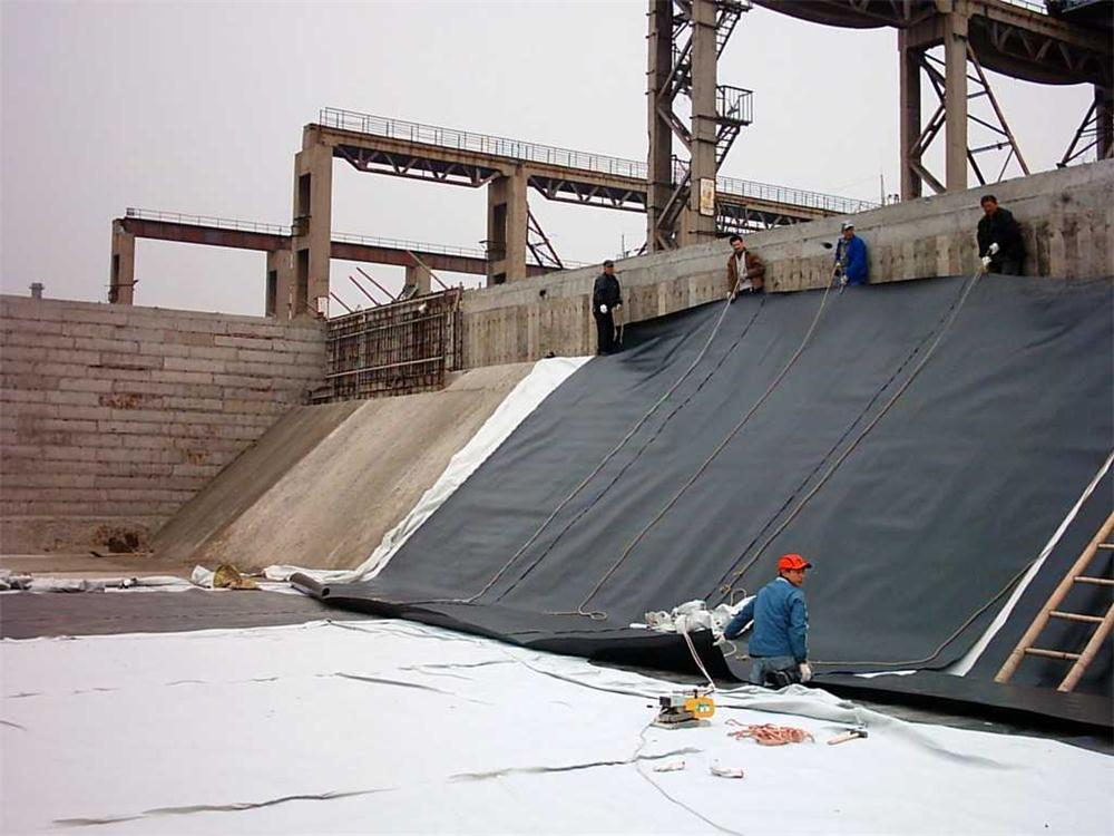
Most spec sheets for geogrids throw a wall of numbers at you: aperture size, tensile strength at 2% strain, junction efficiency, long-term design strength. You don’t need a civil engineering degree to make sense of them, but you do need to stop reading them like a warranty card. Start with what the grid actually has to do in your project—hold soil in place, bridge a soft spot, reinforce a retaining wall—then work backward from the numbers that describe that behavior. Ignore the marketing copy that leads with the highest ultimate tensile strength. That number is tested in a lab on a clean strip, not in your wet, compacted fill.
The first thing to scan is the aperture size and shape. A grid with square or rectangular openings has to be large enough to let aggregate lock through it. If your backfill is crushed stone with 3/4-inch particles, an aperture of 1 inch or less will choke the interlock and the grid becomes just a plastic sheet. Look for the minimum aperture dimension, not the diagonal. Next, check the tensile strength at 2% or 5% strain, not the ultimate. Soil rarely allows a grid to stretch more than a couple percent before the structure moves too much. A grid with 40 kN/m at 2% strain beats a grid with 80 kN/m ultimate that hits 10% strain before it starts working.
Finally, look for the installation damage reduction factor and the creep reduction factor—these are the silent killers of long-term performance. A spec sheet that lists only the short-term tensile strength is hiding the number you should actually design with. Multiply the lab strength by the reduction factors to get the long-term allowable strength. If the sheet doesn’t give you those factors or tells you to ask the manufacturer, that’s a red flag. You don’t need to memorize every test standard; you just need to know which three numbers drive the design: aperture, low-strain strength, and long-term reduction. Everything else on the sheet is either a footnote or a sales pitch.
How Aperture Size Shapes Soil Confinement on Steep Slopes
Aperture size isn't just a detail on a spec sheet—it's the primary lever controlling how much soil can shift before the system locks it in place. On steep slopes, where gravity works around the clock, smaller openings create a tighter web that grabs individual grains and small aggregates almost immediately. This rapid engagement prevents the early stages of rill formation, which often begin with just a few loose particles starting to roll. By shortening the distance any particle can travel before encountering resistance, the system keeps the surface layer intact, reducing the chance that a minor disturbance turns into a continuous erosion channel.
Yet there's a trade-off that emerges once water enters the picture. Extremely small apertures can trap fine particles at the surface, leading to localized clogging that slows infiltration and increases runoff velocity. On a 35-degree slope, that extra runoff gains destructive energy quickly, potentially undercutting the very confinement you're trying to achieve. A slightly larger opening—often in the range of 6 to 10 millimeters—allows fine soil to pass through while still capturing the larger aggregates and gravel that provide structural backbone. This selective retention keeps the slope breathable, letting water drain without carrying away the load-bearing fraction of the soil.
The real skill lies in matching aperture to slope angle and soil texture. A sandy, well-drained soil on a steep grade might benefit from a tighter mesh because the risk of clogging is low and the particles are small enough to slip through almost anything. A clay-rich slope, however, demands a more open pattern to avoid creating a slick, impermeable layer just beneath the surface. Field observations from erosion control projects show that slopes where aperture size was adjusted after initial rainfall events—loosening the mesh where pooling occurred—outperformed those with a single, uniform opening by a factor of two in reducing soil loss over a season. That adaptive approach treats aperture not as a static parameter but as a dynamic response to how water and soil interact on that specific slope.
Polymer Choices That Survive Aggressive Soils
Aggressive soils rarely announce themselves until a buried polymer starts to fail. Sulfate-rich clays, acidic mine tailings, and saline groundwater all attack common materials through hydrolysis, oxidation, or plasticizer leaching. In these conditions, high-density polyethylene (HDPE) and polypropylene (PP) hold up well because their molecular backbones contain no ester or amide linkages that water and acids can cleave. PVC also tolerates many acids and alkalis, but its performance can drop if additives migrate out over time. For acidic sulfate soils, HDPE is often the first choice due to its resistance to stress cracking and its weldability in field repairs.
Alkaline and salt-laden soils present a different set of challenges. Polypropylene and cross-linked polyethylene (PEX) resist caustic conditions without losing flexibility. Polyurethane coatings sometimes serve as an additional barrier, though prolonged contact with hot, high-pH water can trigger hydrolysis. Epoxy systems handle strong bases well but may soften or blister in acidic ground. A common mistake is to select a polymer based only on a single chemical rating. Field performance depends on temperature fluctuations, oxygen availability, and the presence of microorganisms that generate organic acids. Testing coupons in actual soil leachate, not just standard lab solutions, gives a far more reliable picture.
Beyond chemical compatibility, aggressive soils accelerate mechanical failure. A polymer that resists acid in a lab can still crack under sustained load if its environmental stress crack resistance (ESCR) is too low. Bimodal HDPE grades are favored for buried pipelines in aggressive terrains because they combine high stiffness with exceptional ESCR. Adding carbon black not only shields against UV during above-ground storage but also improves long-term weathering in exposed transition zones. Some engineers specify a minimum ESCR of 1,000 hours for pipes in acid sulfate or saline soils. Ultimately, the most durable choice pairs a chemically inert backbone with a resin grade tailored for slow crack growth, not just short-term chemical exposure.
Avoiding the Most Common Geogrid Installation Mistake
On paper, geogrid installation looks straightforward: roll it out, cover it with fill, and move on. In the field, though, the same error shows up again and again — crews lay the grid down loose, with wrinkles and slack, then immediately bury it under a thick layer of aggregate. The result is a reinforcement layer that never actually engages under load. Instead of carrying tensile stress, the geogrid simply shifts and settles, leaving the pavement or wall to do all the work on its own.
The fix is less about expensive equipment and more about changing the sequence. Before any fill touches the grid, someone needs to walk the entire length and pull it taut — not just with a tug at one end, but section by section, pinning or staking the edges as you go. A simple come-along or tension bar works better than muscle alone, especially on longer runs. Once the grid lies flat with no visible undulation, only then should the first lift of fill be placed. And that first lift should be thin enough to allow hand-tamping without ripping the grid out of position.
Another quiet mistake that often accompanies the loose-grid problem is ignoring the roll direction. Geogrids have a primary strength axis, and if that axis runs perpendicular to the main stress path, you get little benefit no matter how tight the installation. Check the manufacturer's markings before unrolling, and make sure the strongest direction lines up with the direction of expected strain — usually parallel to the slope face or along the traffic lane. A few minutes of alignment and tensioning at the start save a costly rework later, when the fill is already down and the mistake is buried.
Designing for Seismic Loads With Uniaxial Reinforcement
Reliance on uniaxial reinforcement under seismic loading is rarely a first choice, but it can be justified for members whose nonlinear response is expected to stay aligned with a single axis. The obvious risk is that reversed ground motion does not respect that alignment. Once cracking initiates perpendicular to the bar direction, there is no secondary steel to bridge the opening, and the member may lose integrity before it reaches its calculated flexural capacity. This makes the approach better suited to low-rise diaphragms, stair cores with limited openings, or secondary elements where ductility demands are modest.
Capacity design becomes the controlling framework. The designer must force yielding into well-confined zones where uniaxial bars can develop their full strain capacity, while keeping all other regions elastic. For a wall or slab with only one layer of reinforcement, that means checking transverse shear, out-of-plane bending, and torsional effects against the overstrength of the primary bars, not their nominal yield force. Anchorage and lap splices often dictate the actual failure mode: a poorly detailed lap can slip at half the expected drift, turning a ductile flexural mechanism into a brittle bond failure.
Verification relies less on prescriptive rules and more on direct simulation or testing. Because the system has no orthogonal reinforcement to redistribute stress after local yielding, small construction tolerances—bars rotated a few degrees, ties misplaced, cover reduced—can shift the plastic hinge location and reduce drift capacity. Nonlinear time-history analysis with fiber sections can capture some of this sensitivity, but physically testing a representative subassembly under reversed cyclic loading still provides the clearest evidence that the single-axis mechanism will form and survive. Many seismic codes permit this simplification only in areas of low seismicity or with additional overstrength factors that compensate for the missing transverse steel.
FAQ
Uniaxial geogrids are stretched in one primary direction during manufacturing, which aligns the polymer molecules for much higher tensile strength along that axis. For tall walls, this means you can place the strong direction horizontally across the wall face, directly countering the lateral earth pressure where it matters most.
Spacing depends on the wall height, facing type, and fill soil friction angle. Typically you start with 12 to 24 inches between layers for segmental blocks, then run a compound stability check. Tighter spacing near the bottom handles higher load, while upper layers can be spread out if global safety factors allow.
Yes, but you need to verify pullout resistance and long-term creep. Fines reduce drainage and increase pore pressure, so a geotextile separator behind the reinforced zone often becomes necessary. If the fine content stays below 35 percent and compaction is controlled, uniaxial grids can still deliver reliable performance.
Many designers focus on tensile capacity but ignore the load transfer at the wall face. The connection can govern failure under surcharge or seismic loading. You should check the manufacturer's connection data at the project's normal load, because a grid that is strong in the middle is useless if it slips out from between the blocks.
Angular aggregate interlocks through the grid apertures, creating a mechanical bond that resists pullout. If the aperture is too small relative to the stone size, the aggregate particles bridge across openings and never fully seat. A larger aperture with a proper ratio of aperture to median particle size gives better interlock and higher pullout capacity.
Bulging usually comes from inadequate compaction near the edge or too much vertical spacing between wraps. Use a lightweight plate compactor within two feet of the face, and wrap each layer tightly over the previous lift. Secondary reinforcement like short biaxial strips at the face can also hold the edge during construction.
There is no fixed limit, but beyond about 40 feet you often see two-stage construction or tiered walls. Global stability, foundation settlement, and construction sequence become bigger challenges than tensile strength. At that scale, instrumented monitoring during fill placement is a smart move.
People choose a product based on short-term pullout tests without adjusting for creep and installation damage. A temporary slope might stand for a year, but if it becomes permanent, the grid needs a creep reduction factor and partical damage factor applied to the lab strength. Otherwise the design factor of safety is much lower than assumed.
Conclusion
Uniaxial geogrids earn their place when a retaining wall or slope demands tensile resistance along a single, predictable axis—think near-vertical walls with uniform backfill pressure or long slope faces where gravity pulls consistently downhill. The spec sheet becomes less intimidating once you ignore the headline tensile number and look instead at creep-limited strength, junction efficiency, and strain at working load; those values tell you how much the grid will actually resist over decades, not just on day one. Aperture size is not a cosmetic detail. Openings that are too large for a silty backfill will let fines wash through and weaken interlock; too small and coarse aggregate can bridge, leaving voids. On steep slopes, matching the aperture to the soil gradation and lift thickness prevents face bulging and keeps each layer locked under compaction.
Polymer selection separates long-term performance from early failure in aggressive environments. HDPE handles a wide pH range and resists chlorides, but polypropylene often performs better where high temperatures and oxidative conditions overlap; confirm chemical compatibility with site soils and any de-icing salts before specifying. The mistake that shows up most often in the field is failing to pull the geogrid taut before placing backfill. Wrinkles and slack folds become zones where the grid cannot engage the soil, effectively shortening the reinforcement length and inviting localized settlement. For seismic zones, uniaxial reinforcement design shifts from static pullout to dynamic load cycles, requiring longer embedment, tighter vertical spacing, and face connections that can tolerate differential movement without snapping. Done right, those details turn a simple grid into a ductile system that holds through ground shaking.
Contact Us
Contact Person: Jennifer LEE
Email: [email protected]
Tel/WhatsApp: 8618553418999
Website: https://vip.e-baixing.com/wenfengshitong