

Top Alloy Resistor Picks for Precision Circuit Designs
2026-11-16
When precision is non-negotiable, every milliohm counts—and the right alloy resistor can be the difference between a stable reading and a drifting signal. But wading through datasheets for low TCR and tight tolerance often feels like a treasure hunt with no map. That’s why we’ve rolled up our sleeves and put a shortlist of standout alloy resistors through their paces, focusing on real-world thermal behavior and long-term drift, not just headline specs. From current-sense amplifiers to high-accuracy voltage dividers, these picks lean on practical insights from Milliohm to cut through the noise. Curious which components actually held their precision under load? Let’s find out.
Alloy Resistors That Hold Their Value After Soldering Heat
Alloy resistors maintain their specified resistance even after a brief encounter with molten solder because the resistance element is a solid metal alloy, not a composite film. Metals like nichrome, manganin, and constantan have an inherently stable lattice structure that doesn't reorganize under typical soldering temperatures, so the nominal value and tolerance stay put when the joints cool.
What often gets overlooked is repeatability. A resistor that sees one soldering cycle may drift a little, but a well-made alloy part will return close to its original reading after the board reaches room temperature. The low temperature coefficient of resistance in these alloys keeps the shift small, and there's no glass binder to develop microcracks from thermal shock. As a result, multiple rework cycles don't cause the same cumulative value change you might see with some film-based parts.
This behavior matters most in circuits where a few hundred parts per million of drift can throw off calibration. Precision current sensing, voltage dividers, and feedback networks rely on alloy resistors because their post-soldering values are predictable, which reduces the need for trim adjustments after assembly.
When Bulk Metal Foil Beats Thin Film for Tiny Signal Paths
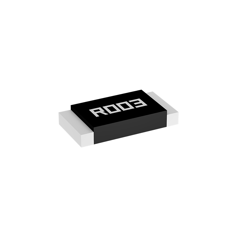
In precision analog front ends, the choice between bulk metal foil and thin film resistors often comes down to how the component behaves under real electrical and thermal stress. Tiny signal paths—think sensor bridges, weigh-scale inputs, or low-level DAC outputs—expose the weaknesses of thin film's sputtered nichrome layer. Bulk metal foil, by contrast, is a cold-rolled, stress-relieved alloy that maintains its resistance value almost regardless of applied power or ambient temperature shifts. That means fewer microvolts of error creeping into a 24-bit measurement.
Another advantage shows up in long-term stability and noise. Thin film resistors can drift measurably after soldering or thermal cycling, and their current noise index is often higher because of the granular structure of the deposited film. Bulk metal foil parts, with their homogeneous metal element and planar geometry, deliver extremely low current noise and near-zero TCR over a wide range. In a tiny signal path where every nanovolt counts, that combination keeps the baseline quiet and predictable.
Perhaps the most overlooked difference is mechanical. Thin film elements on ceramic substrates can micro-crack under board flex or repeated temperature swings, causing intermittent resistance shifts that are hard to diagnose. Bulk metal foil resistors are typically bonded to a flexible substrate with stress-relieving patterns, so they tolerate vibration and thermal expansion without changing value. For portable or handheld instruments with small, tightly packed boards, that mechanical resilience often decides whether the signal stays clean years after the product ships.
A Practical Look at Tolerance and Tempco in Precision Dividers
Precision dividers live or die by two specifications that are easy to gloss over until they bite you: resistor tolerance and temperature coefficient (tempco). Tolerance tells you how far the actual ratio can stray from the ideal at room temperature, but it says nothing about what happens when the board heats up. A pair of resistors with a tight initial ratio can still drift apart if their tempcos are mismatched, turning a precision reference into a thermometer.
Instead of treating tolerance and tempco as separate line items, it helps to think of the divider as a system. The absolute resistance values matter less than how the two resistors move together. If you pick two resistors from the same batch with similar tempco, the ratio error over temperature can be orders of magnitude smaller than the individual tempco figures suggest. In practice, this means paying attention to the relative mismatch, not just the datasheet extremes.
One common trap is assuming that a 0.1% tolerance divider will hold that accuracy across temperature. It won't unless the tempco mismatch is also specified or controlled. For example, a ±25 ppm/°C tempco mismatch over a 40°C swing adds up to 0.1% additional ratio error. So when you're budgeting error, add the tolerance error and the tempco-induced error as independent terms—and remember that the worst-case sum is usually pessimistic, but still worth checking.
Avoiding the Trap of Over-Specified Current Sense Resistors
Current sense resistors are often selected with far more precision than the application actually needs. Engineers chase ultra-tight tolerances, low temperature coefficients, and high power ratings, assuming these specs guarantee accuracy. In reality, the measurement circuit’s layout, amplifier offset, and trace resistance frequently introduce errors that dwarf the resistor’s own deviation. Spending extra on a 0.1% component while ignoring a few milliohms of unbalanced copper can be a costly oversight.
A more practical approach starts with the signal-to-noise requirement and the expected current range. From there, choose a resistance value that produces a readable voltage without excessive drop or heat. Then pick a tolerance and thermal rating that stay well within the allowable error budget after accounting for all other contributors. This often reveals that a standard 1% or even 5% resistor in a slightly larger package works just as well as a high-precision part, while costing less and easing procurement.
Over-specification also hurts long-term reliability. Resistors with extremely tight specifications may be sourced from limited vendors, have longer lead times, or require special handling. By concentrating on the whole measurement chain rather than a single component’s datasheet, designers can build robust current sensing that performs consistently in production without paying for unnecessary precision.
Thermal EMF: The Hidden Error in Your Precision Layout
Thermal EMF quietly undermines precision analog circuits by converting small temperature differences across dissimilar metal junctions into voltage offsets. When you join copper traces, solder, component leads, or connector pins, you accidentally create thermocouples. Even a couple of degrees across one of those junctions can generate tens of microvolts, which is catastrophic when you are trying to resolve a 12-bit or 16-bit signal in the millivolt range.
In a real PCB, the trouble hides in plain sight. A precision op-amp sitting next to a linear regulator sees a gentle thermal gradient across its input pins. One input trace runs over a ground pour that heats unevenly, while the other stays cool. A banana jack with nickel plating mates with a copper wire, and the lab warms up by three degrees. Suddenly the zero point shifts between morning and afternoon, and no amount of firmware averaging can fix a changing physical offset.
The practical fix is to treat every microvolt path as a thermal design problem. Keep input pairs physically close and route them symmetrically so they share the same isotherm. Place precision front-ends away from regulators, shunt resistors, or anything that dissipates real power. Use low-thermal-EMF connectors for critical hookups, minimize relay contacts in the signal path, and let the board reach thermal equilibrium before calibration. Once you start seeing layout as the art of preventing tiny temperature differences, the hidden error becomes manageable.
From BOM to Board: Matching Resistor Networks for Real Stability
A bill of materials lists resistor values with neat little tolerance percentages, and on paper that seems like the end of the story. But anyone who has chased a drift fault across a production run knows the real challenge starts the moment those parts leave the reel. Matching resistor networks is less about picking precision parts and more about acknowledging that every solder joint, every thermal gradient, and every trace of copper adds its own signature to the final circuit. The gap between a perfectly matched network in simulation and a stable one on the board is where most designs quietly fail.
Temperature coefficients rarely move alone. Two resistors rated at ±25 ppm/°C can still diverge by 50 ppm if they sit on opposite sides of a heat source or if one is buried under a larger component. That divergence multiplies in divider networks, instrumentation amplifiers, and feedback loops where ratio stability matters far more than absolute value. The smart move is to stop treating resistors as discrete components and start seeing them as a system that shares silicon, shares thermal mass, and shares a layout. Integrated resistor arrays, for example, often guarantee ratio tracking to within a few ppm because the elements are fabricated together and sit on the same substrate—something no amount of individual precision can replicate.
From BOM to board, the path to stable resistor networks runs through deliberate symmetry. Place matched pairs in the same orientation, away from board edges and high-current traces. Use copper pours to equalize temperature, not just to manage ground loops. And when the design can tolerate it, lean on thin-film networks or matched sets that specify tracking rather than absolute tolerance. The goal is not to eliminate every source of error—that is a fool's errand—but to make the errors common-mode so they cancel at the node that matters. Stability is not a component property; it is a layout discipline.
FAQ
Alloy resistors typically offer a tighter combination of tolerance, temperature coefficient, and long-term drift than standard thin film. For a precision signal path, that means the initial accuracy holds up better over temperature swings and years of operation, which reduces the need for software compensation or manual trimming.
For gain-setting pairs, I usually start with bulk metal foil types like the Vishay VPG Z202 or the older S102 series when the budget allows. They stay within a few ppm/°C and have almost negligible load-life drift, which keeps differential gains stable without needing matched resistor arrays with extra pads.
If the sense current is above roughly 1 A and the target accuracy is better than 1%, I go with a 4-terminal Kelvin connection. Lead resistance in a 2-wire package can easily swamp a low milliohm value, so separating force and sense lines gives you the actual drop across the resistive element, not the solder joints and traces.
The main issue is parasitic inductance in larger metal strip or wirewound alloy parts. For high-side current sensing in a switching regulator, that inductance can cause voltage spikes that corrupt the measurement. I either pick a low-inductance chip-style alloy resistor or add a small RC filter right at the sense amplifier inputs.
Look closely at the derating curve, the hot-spot temperature rating, and the resistive material's temperature coefficient of resistance. An alloy resistor rated for 5 W at 25°C may only handle 2 W at 100°C, and TCR can shift non-linearly near the high end. I usually pick a part with at least 50% headroom on power and a specified TCR over -55°C to +155°C.
Yes, especially with chip-style metal alloy current sense resistors. A 1 mΩ part in a 2512 package can handle several watts and still provide clean Kelvin sensing, saving a lot of board area compared to a bolt-in shunt. Just be careful with copper trace resistance; keep the sense traces short and use separate pads for the current path.
Thermal EMF at the junction between the resistor termination and the PCB copper can introduce microvolt-level offsets that vary with temperature gradients. I choose alloy resistors with low-thermal-EMF terminations, such as those that use copper-manganese or special alloy leads, and I try to keep the resistor away from high-dissipation components so the temperature across the pads stays balanced.
Conclusion
Precision circuit designs often hinge on resistor behavior after soldering. Alloy resistors that hold their value despite thermal shock remove a persistent source of drift, while bulk metal foil can outperform thin film in tiny signal paths where microvolt-level integrity matters. When building precision dividers, tolerance and tempco are not just datasheet numbers; they interact with layout and load, so a practical look at matching matters more than chasing an ideal spec. Over-specifying current sense resistors can inflate cost and board space without measurable benefit if the actual sense voltage and noise floor don't demand it; instead, pick a value that keeps the sense voltage comfortably above the amplifier offset while leaving margin for inrush or fault conditions.
Thermal EMF remains a hidden error in precision layouts, especially where dissimilar metals meet and temperature gradients exist; even a few microvolts per degree can swamp a 16-bit reading. Choosing low-thermal-EMF alloy resistors and symmetric copper routing helps. From BOM to board, matching resistor networks for real stability means tracking ratio drift over temperature and time, not just initial tolerance; laser-trimmed networks on a common substrate often beat discrete parts for ratio tempco, but you still need to verify aging behavior. A reliable selection balances post-soldering stability, foil-vs-film tradeoffs, divider matching, sensible current-sense ratings, and low thermal EMF so the final board meets its intended precision without over-engineering.
Contact Us
Contact Person: Yuying Gao
Email: [email protected]
Tel/WhatsApp: +86 18926013721
Website: https://en.milliohm.net/