

Top Cleanroom Engineering Strategies for High-Performance Controlled Environments
2026-08-19
Achieving a truly high-performance cleanroom isn't just about meeting ISO classifications—it's about engineering every detail, from airflow patterns to material selection, with precision and foresight. As controlled environments become more demanding, the gap between standard compliance and operational excellence continues to widen. Discover the core strategies that separate exceptional cleanrooms from the rest, and see how GENO Pharmatech applies these principles to deliver environments built for uncompromising performance.
Designing Airflow That Actually Sweeps Particles Away
Most dust collection setups fail for a simple reason: they pull air, but they don't think about where the particles are actually going. You can crank up the fan and still watch a haze of fine dust drift past the hood, because the suction zone is too shallow and the surrounding air just tumbles in from all sides. What works is treating airflow like a fluid blade that pushes the contaminant toward the inlet. In a grinding booth, for example, a wide, low-velocity crossdraft moving from the operator's breathing zone toward the back wall will carry particles away far more reliably than a high-velocity round duct opening placed somewhere above the work.
The shape and position of the capture opening matter more than raw airflow volume. A narrow slot running the full width of a workbench creates a uniform pull that reaches farther than a round hood with the same exhaust rate. In cleanrooms, unidirectional downflow looks good on paper, but any equipment, thermal plume, or worker movement creates dead zones where particles hover instead of being swept to the floor returns. Designers need to map out these obstructions and place low-level exhaust registers to draw the air around them, not just hope the particles will fall out of the airstream.
A practical trick that often outperforms a simple capture hood is the push-pull arrangement. One side blows a gentle sheet of air across the work area, while the opposite side exhausts it. This creates a controlled air curtain that traps fumes and dust inside a moving corridor, preventing them from escaping into the room. It takes less fan energy than a huge side-draft hood and handles intermittent bursts of dust better. Before settling on a design, watch where the particles actually go during normal operations, then shape the airflow to intercept that path. The goal is not just moving air, but moving air with intent.
Where Most Filtration Strategies Fall Short
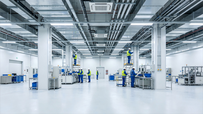
Ask any plant manager where their filtration system underperforms, and you'll rarely hear about the filter itself. The media gets blamed, the housing gets blamed, even the upstream process gets blamed—but the real culprit is almost always the assumption that a one-size-fits-all pore size can handle every load condition. In reality, most strategies fail because they're designed for a steady-state flow that never exists. Particles arrive in bursts, viscosity swings with temperature, and the filter that worked at 2 p.m. is blind by 2 a.m. If you're not accounting for those swings, you're not filtering; you're just delaying the shutdown.
Another common failure point is the obsession with nominal ratings over actual retention efficiency. A filter that claims "10 micron nominal" might stop a few large chunks while letting a river of smaller fines pass straight through to your heat exchanger or injection pump. Those fines accumulate in places you can't easily inspect, and by the time pressure drop tells you something's wrong, the damage is already done. Smart operators have started tracking beta ratios and dirt-holding capacity instead of marketing numbers—because a filter that holds three times more contaminant before plugging isn't just better; it's the difference between a planned changeout and an emergency bypass.
Finally, too many strategies ignore the economics of early-stage versus late-stage filtration. A cheap sack filter on the inlet might save pennies per gallon, but if it lets abrasive particles reach a critical servo valve downstream, the repair bill wipes out a year of savings. The smartest systems put the coarsest filter first to knock out the big stuff, then stage progressively finer media only where it actually protects a sensitive component. Skipping that staging—or over-filtering everything at the inlet—is how you end up changing elements every week and still seeing wear on your most expensive parts.
Pressure Differentials That Hold Up Under Real Use
A printed pressure differential number only tells you what the unit did on a calibration rig. Real use adds thermal swings, vibration, chemical exposure, and long idle periods—each one enough to relax a seal or warp a housing. The meaningful test is whether the separation still holds after a few hundred cycles, not at minute zero.
Durable designs address this by choosing elastomers with low compression set, adding reinforcement ribs where flex tends to occur, and machining mating surfaces slightly wider than strictly necessary. Some manufacturers also avoid single-point sealing altogether, opting for two or three redundant contact zones that share the load. It costs more on the bill of materials, but it prevents the slow bleed that leads to pressure decay and bypass.
On the floor, that translates into steady airflow, longer intervals between filter changes, and fewer callouts for unexplained performance drops. A differential that holds up under real use doesn't just meet a spec—it keeps the process stable when ambient conditions shift and maintenance schedules slip. That reliability shows up in the operating logs, not in a datasheet footnote.
Material Selection for Low-Shedding Surfaces
A surface’s tendency to shed particles depends more on how the material responds to friction and flexing than on its initial cleanliness. Hard, chemically inert polymers such as PEEK and virgin PTFE tend to release fewer particles than softer or compounded plastics because they resist micro-abrasion and don’t rely on fillers that can break free. For metals, electropolished 316L stainless steel or hard-anodized aluminum with a sealed oxide layer often performs better than raw machined surfaces, where micro-burrs and grain boundaries act as particle traps.
In cleanroom and medical device applications, material choice has to account for repeated sterilization or cleaning. Steam, hydrogen peroxide, or solvent exposure can degrade surface coatings and generate debris. Here, dense thermoplastics and certain fluoroelastomers hold up better than powder-coated parts or open-cell foams. Avoid materials that shed fibers by design—woven textiles with staple fibers, for instance—and specify continuous-filament alternatives or hard, monolithic surfaces whenever contact with product or airflow is possible.
Surface finish matters as much as base material. Even a relatively stable polymer will shed if its surface is rough, scratched, or contains mold release residue. A low-shedding spec should include a maximum Ra value, typically below 0.8 µm for critical surfaces, along with a cleaning protocol that removes loose particles before installation. Pairing the right material with a finish that doesn’t trap debris gives a more predictable outcome than relying on material alone.
Smart Sensor Layouts That Catch Problems Early
Smart sensor placement isn’t about blanketing a machine with as many devices as possible—it’s about reading failure signatures before they escalate. Vibration probes mounted near bearing housings, acoustic sensors aimed at high-wear gear meshes, and thermal arrays tracking heat soak in electrical cabinets form a layered net. The trick is understanding which physical changes precede common breakdowns: a slight imbalance shows up as a specific frequency pattern long before visible wobble, while a creeping temperature differential across a coil hints at insulation fatigue. Engineers who map these early indicators onto physical coordinates build a detection topology that acts like a nervous system, sensing trouble while it’s still a whisper.
Effective layouts often follow the logic of failure modes rather than convenience. Instead of spacing sensors evenly, teams identify stress risers—shaft coupling points, valve stems under cyclic load, cooling fins prone to dust accumulation—and cluster sensors there with overlapping coverage. A pressure transducer next to a filter housing pairs with a differential sensor across the element, catching clogging when flow resistance climbs only 3%, not when bypass alarms trigger. Redundancy isn’t wasted hardware; two accelerometers mounted eighteen degrees apart on a pump casing can distinguish a genuine rotor crack from a loose mounting bolt by comparing phase drift. This kind of deliberate overlap converts raw data into diagnostic confidence early on.
The payoff comes when a sensor network flags a developing issue during a routine run, not after a breakdown. Consider a chilled water loop where three strategically placed ultrasonic flow meters detect micro-cavitation near an elbow—caused by a partially closed valve two floors away—weeks before pipe wall erosion becomes audible. Or a gearbox where a single triaxial accelerometer, positioned against the input shaft bearing cap, picks up a 0.2-order sideband that maintenance software traces to a worn tooth, triggering a fifteen-minute inspection instead of a weeklong teardown. Early catching doesn’t demand exotic hardware; it demands layouts that think like a diagnostician, placing each sensor where its data tells the clearest story about what’s about to go wrong.
Cutting Energy Use Without Breaking Containment
In many negative-pressure laboratories, ventilation systems run at fixed air change rates around the clock, even at three in the morning when no one is inside. This conservative approach keeps containment stable but wastes a striking amount of electricity. By tying room occupancy sensors, biosafety cabinet status, and door contacts into the building automation system, the total supply and exhaust air volumes can be reduced during unoccupied periods while pressure sensors continuously confirm that the negative-pressure gradient has not reversed. As long as the control loop responds quickly, nighttime airflow can often be cut to sixty percent of design value or lower without compromising containment.
What really threatens containment is often not the airflow volume itself but the airtightness of the building envelope. Gaps around piping penetrations, worn door seals, and cable tray openings let air leak in from the low-pressure side, forcing fans to work harder to maintain the required pressure differential. Spending a few days on a blower-door test and sealing these hidden leaks with low-leakage dampers and flexible gaskets is usually cheaper than installing larger fans. Once leakage drops, the supply air needed to hold the same pressure differential also falls, and energy use follows.
Heat recovery devices are sometimes dismissed out of fear that they will break the separation between exhaust and supply air. In practice, run-around coils or plate heat exchangers can transfer heat between two airstreams that never mix, which is ideal for facilities that exhaust large volumes of conditioned air. Combined with variable-speed fans and demand-based pressure control, this approach can cut ventilation energy use by thirty to fifty percent while keeping pressure fluctuations in critical zones even smaller than under fixed-flow operation.
FAQ
Standard cleanrooms often rely on turbulent dilution, but high-performance suites use unidirectional flow—either vertical or horizontal—to sweep particles away from critical processes. The key is achieving uniform velocity of 0.3–0.5 m/s across the entire work zone, which requires careful diffuser placement and regular airflow visualization testing.
Positive pressure keeps unfiltered air out, but it doesn't address particle generation inside the room. High-performance strategies combine pressure cascades with localized exhaust, air returns at low level, and strict protocol on door openings. A 15 Pa differential can be negated by a single rapid door swing, so airlocks and interlocking doors are essential.
Non-porous, chemically resistant materials like stainless steel, epoxy-coated gypsum, or PVC wall panels minimize particle shedding and withstand repeated disinfectant use. Flooring should be seamless with coved corners to prevent microbial buildup. Avoid materials that degrade under UV or vaporized hydrogen peroxide, as this can release fibers or outgas contaminants.
Filter bypass leakage is a common culprit. Even a small gap around a HEPA filter housing can allow 0.5 micron particles to bypass the filter entirely. Regular aerosol challenge testing with photometers, not just particle counts, is needed to verify filter integrity. Also, insufficient air changes during low-occupancy periods can let particles settle and re-entrain when activity resumes.
Implement demand-controlled filtration based on real-time particle counts rather than running fans at constant speed. Use variable frequency drives on fans, but maintain minimum air changes to prevent stagnation. Night setback mode can reduce air changes when no processes are active, as long as pressure differentials stay positive and temperature/humidity limits are not exceeded.
Personnel are the largest source of particles in an operating cleanroom. Proper gowning with low-shedding fabrics, hoods, and shoe covers is a behavioral control that complements engineering controls. A robust protocol includes staged gowning rooms, sticky mats, and periodic training with garment particle testing—not just a checklist on the wall.
ULPA filters are typically reserved for ultra-clean applications like semiconductor lithography below 10 nm or aseptic processing of potent compounds. They demand higher pressure drop and cost more, so they are not automatically better. If your process tolerates a few particles per cubic meter at 0.1 micron, HEPA is sufficient; ULPA becomes necessary only when even a single sub-0.2 micron particle can cause yield loss.
Use smoke studies or air current visualization with foggers under actual operating conditions, not just static. Video record the smoke path across the critical zone and check for turbulence or reverse flow at equipment edges. Additionally, perform velocity mapping with a hot-wire anemometer at multiple heights to ensure uniformity within ±20% of design spec.
Conclusion
High-performance cleanrooms are built around airflow that actually removes contaminants rather than simply recirculating them in a visually uniform pattern. A unidirectional system with HEPA or ULPA coverage is only as effective as its return air path: low-wall returns, raised-floor perforations, and equipment placement must work together so particles are pushed away from critical zones and toward exits. Too many designs treat filtration as a plug-and-play fix, ignoring gasket leaks, gaps around filter housings, and bypass pathways that quietly erode rated efficiency. Equally important are pressure differentials that remain stable under real conditions—when a pass-through door opens, a cart rolls across the threshold, or an exhaust fan ramps down. Static readings on a differential pressure gauge do not guarantee containment; the cascade must hold during dynamic events, which requires active control and routine challenge testing rather than a single commissioning snapshot.
Surface selection directly affects particle generation and cleaning reliability. Painted drywall, exposed insulation, and rough-cut edges shed particles and trap disinfectants, whereas electropolished stainless steel, solid polymer panels, and heat-welded vinyl flooring create low-shedding, damage-resistant boundaries. Sensor placement is another underrated lever: particle counters and pressure transmitters should sit near transfer hatches, equipment exhausts, and other high-traffic spots, not in stagnant corners, because early warning depends on measuring where failures begin. On the energy side, containment does not have to mean running fans at full speed around the clock. Demand-controlled ventilation, variable-speed fan arrays, and reduced air change rates during idle periods can cut power use substantially, but only after particle and pressure data prove that the lower airflow still sweeps and separates clean from less-clean zones. The most resilient facilities treat these six strategies as one integrated system, adjusting each element only when the data supports the change.
Contact Us
Contact Person: Amy Yang
Email: [email protected]
Tel/WhatsApp: 008619330882686
Website: https://www.genopharmatech.com/